


With the white piece back on, you can see how the wipers rotate:
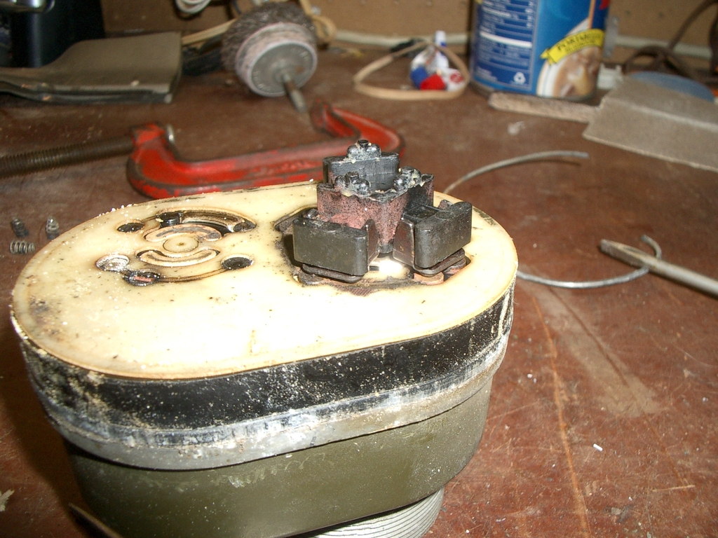
Here's the main wiper assembley, in the off position:
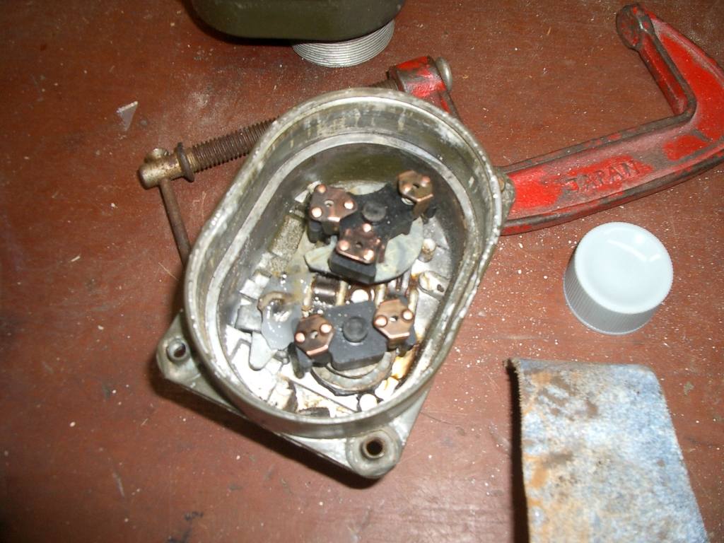
I removed the springs from the contacts, to let is sit flush - normally the contacts are pressed down by three small springs. Here it is in both of the blackout positions, showing the triangular contacts
connecting the inner rings to the outer bumps:
Further opening the switch
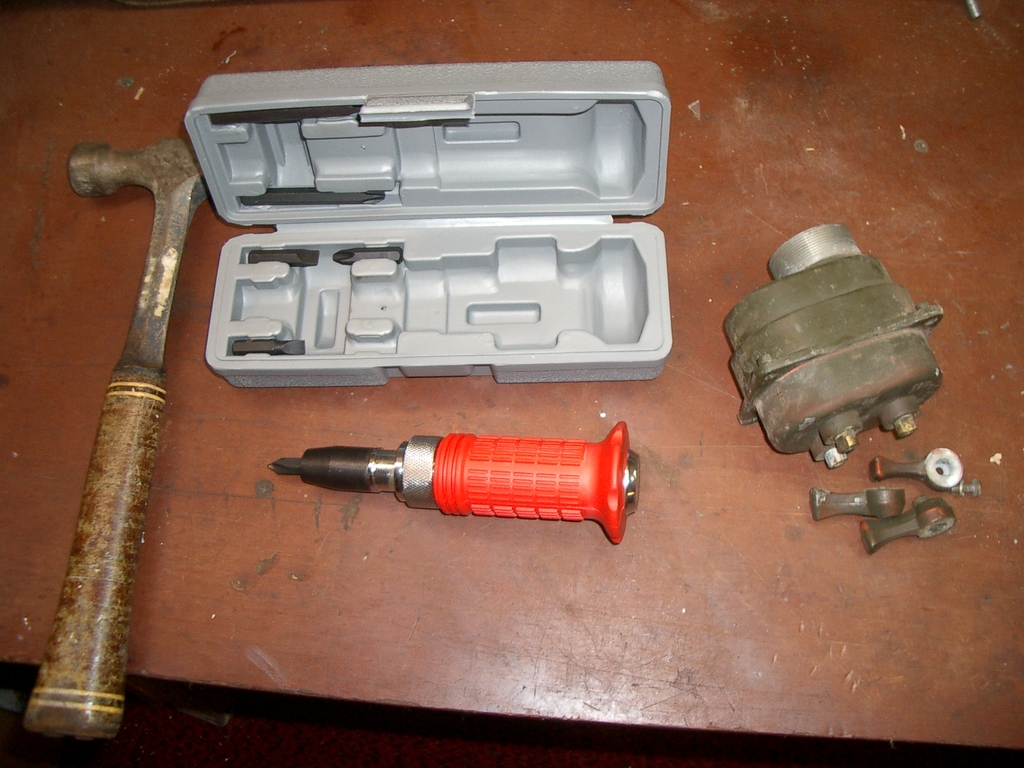
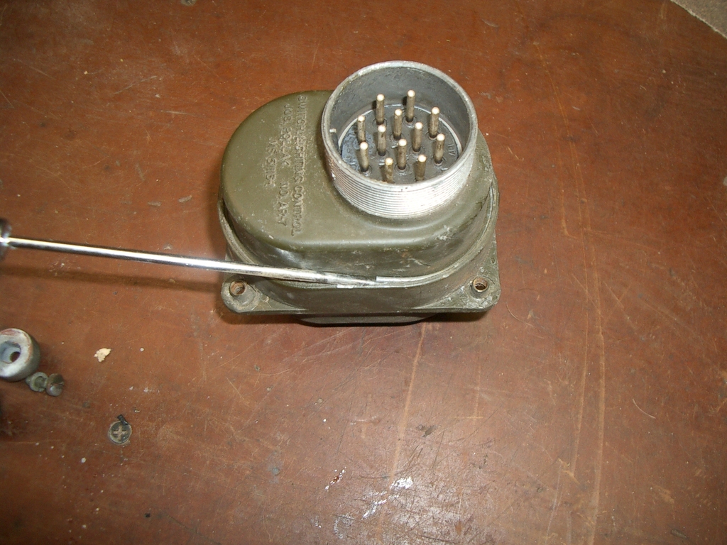
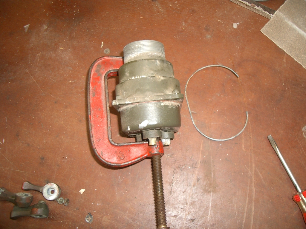
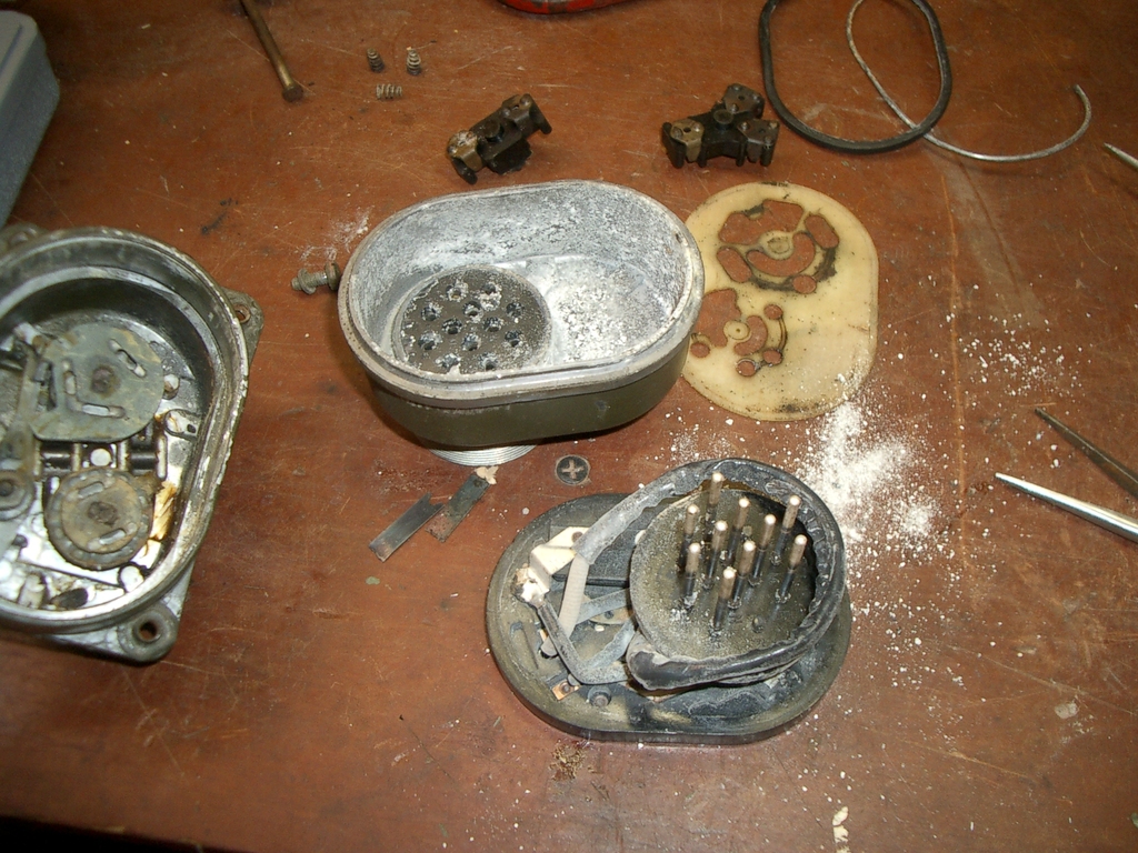
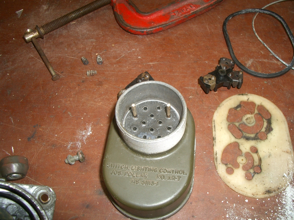
First, remove the O-ring from the housing, being careful not to tear it. A really thin screwdriver down the side can help. Start popping it out of its groove...
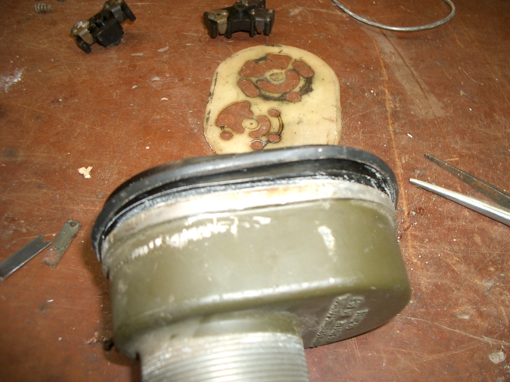
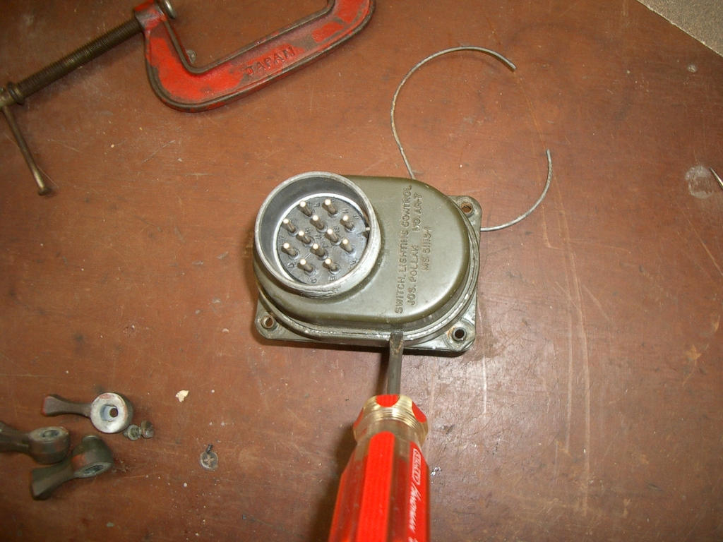
Then get a screwdriver under there and start gently prying all the way around:

The contacts should start to pull through the rubber part of the connector:
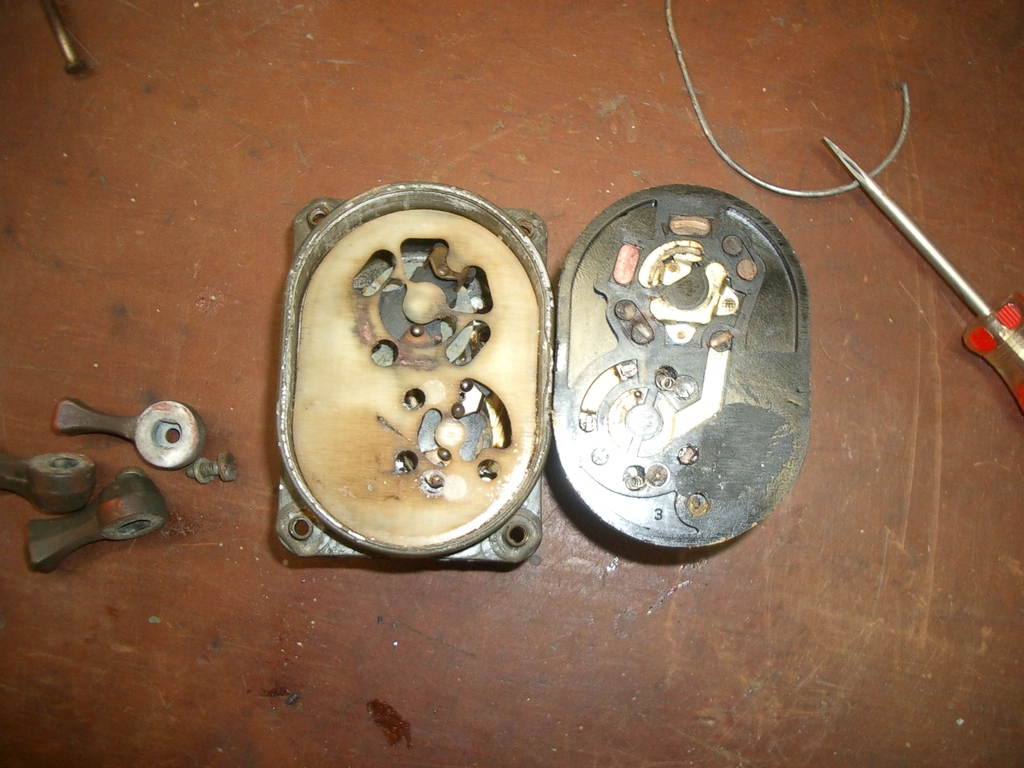
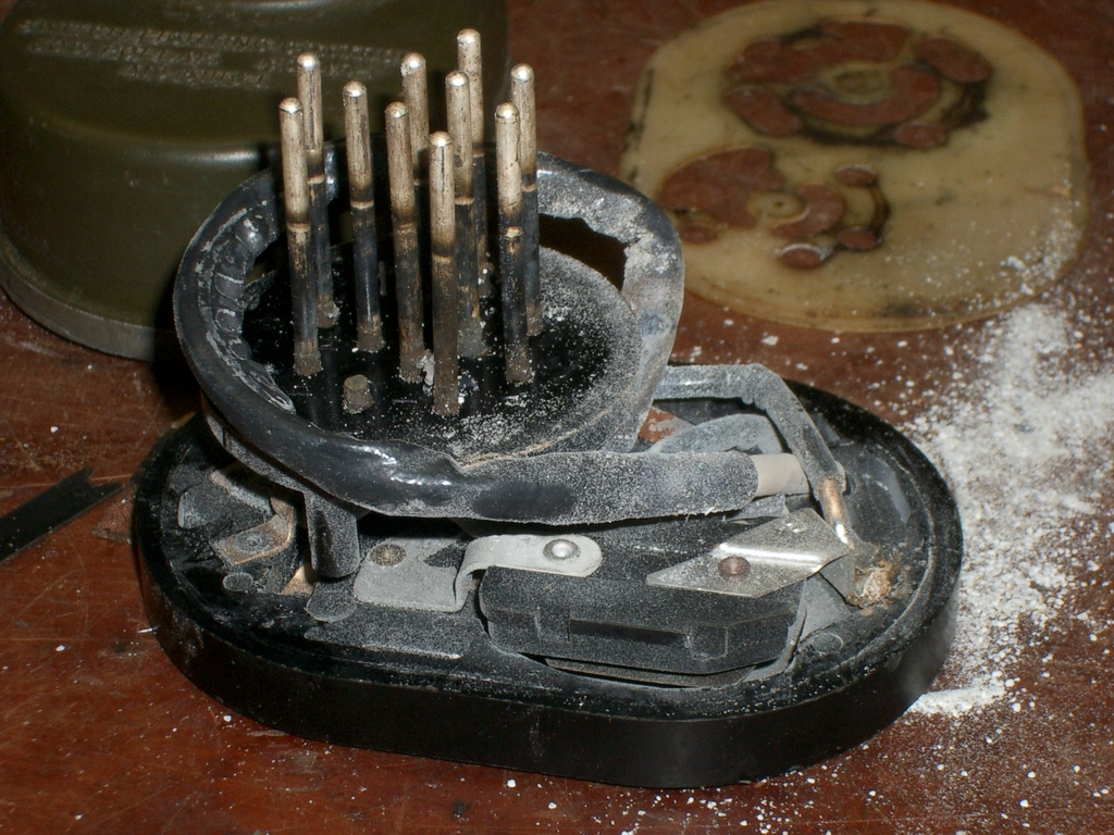
Yours will hopefully all pull through, rather than leaving two sticking up like mine did! Keep evenly prying, until it comes apart:
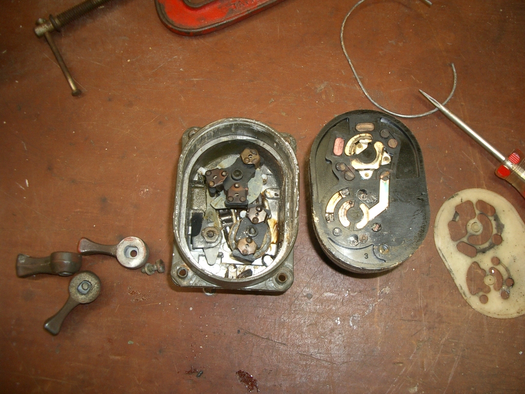
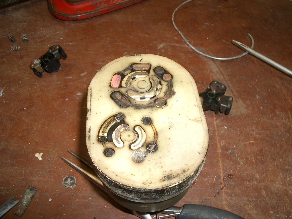
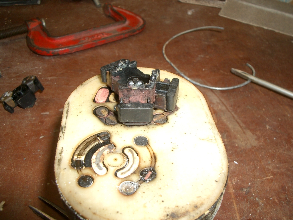
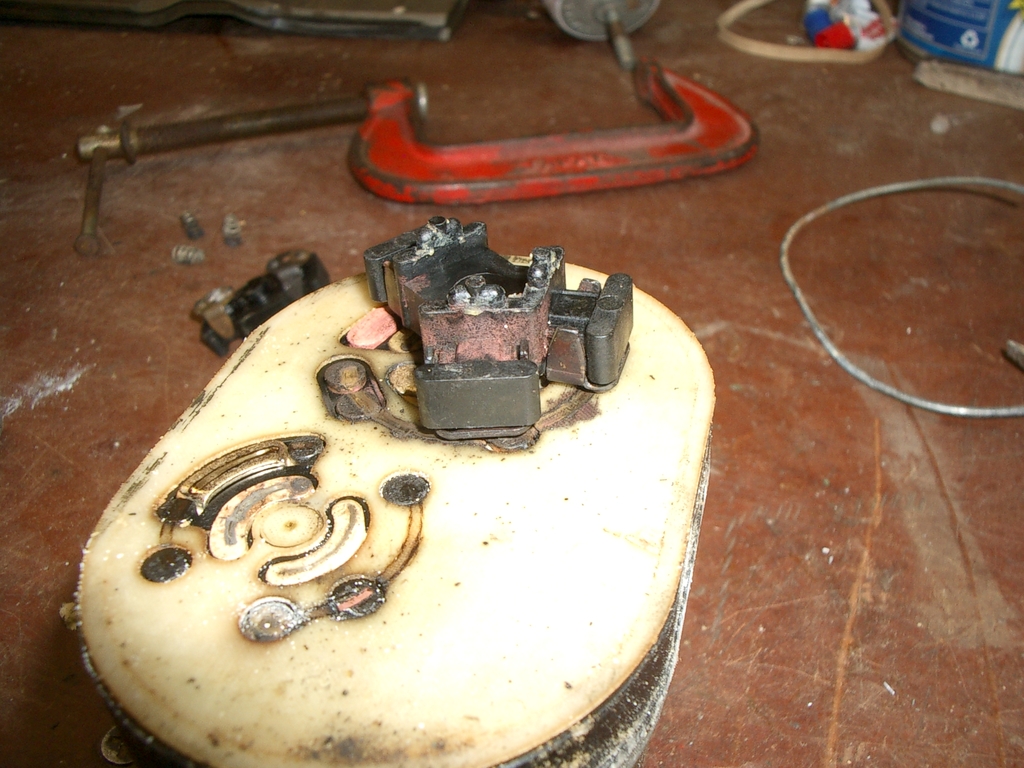
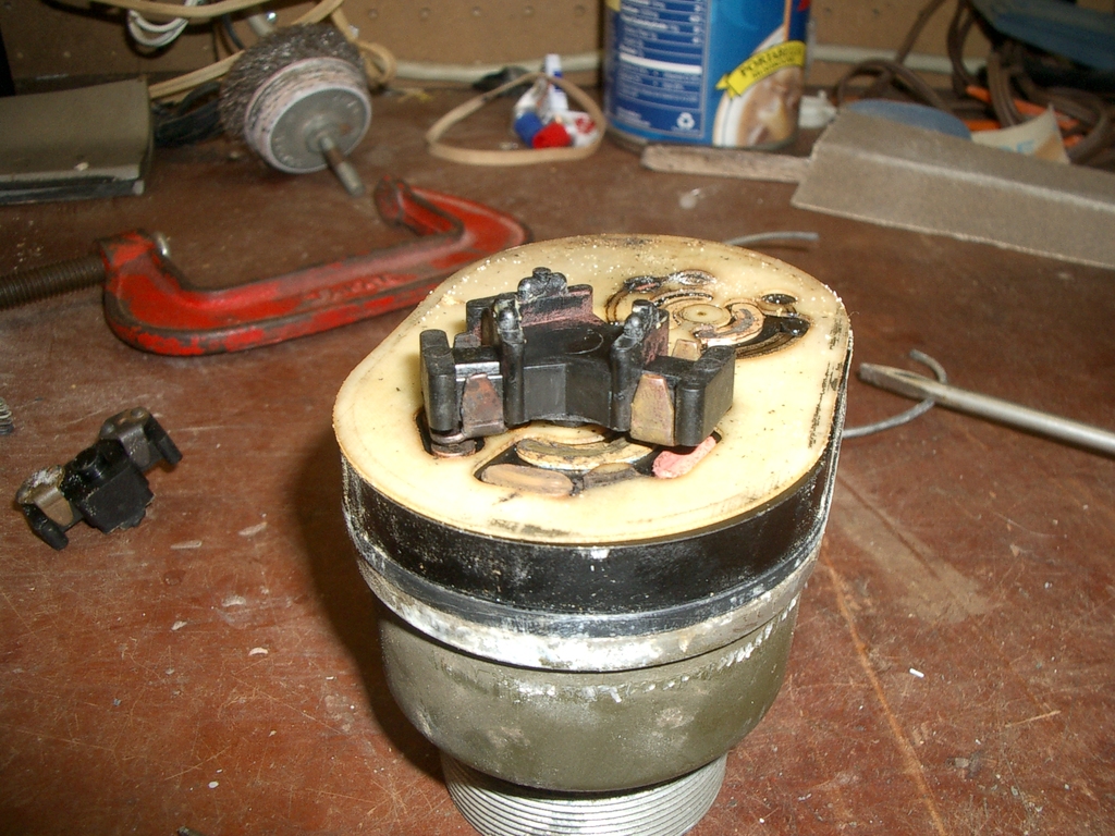
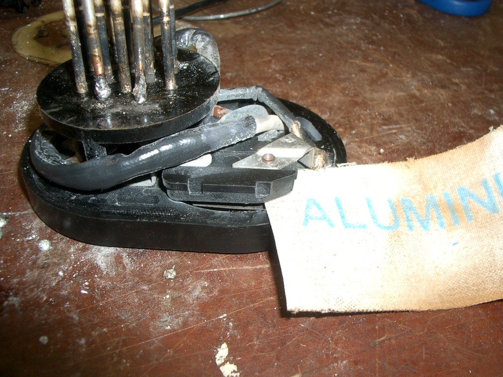
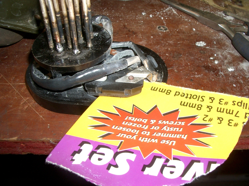
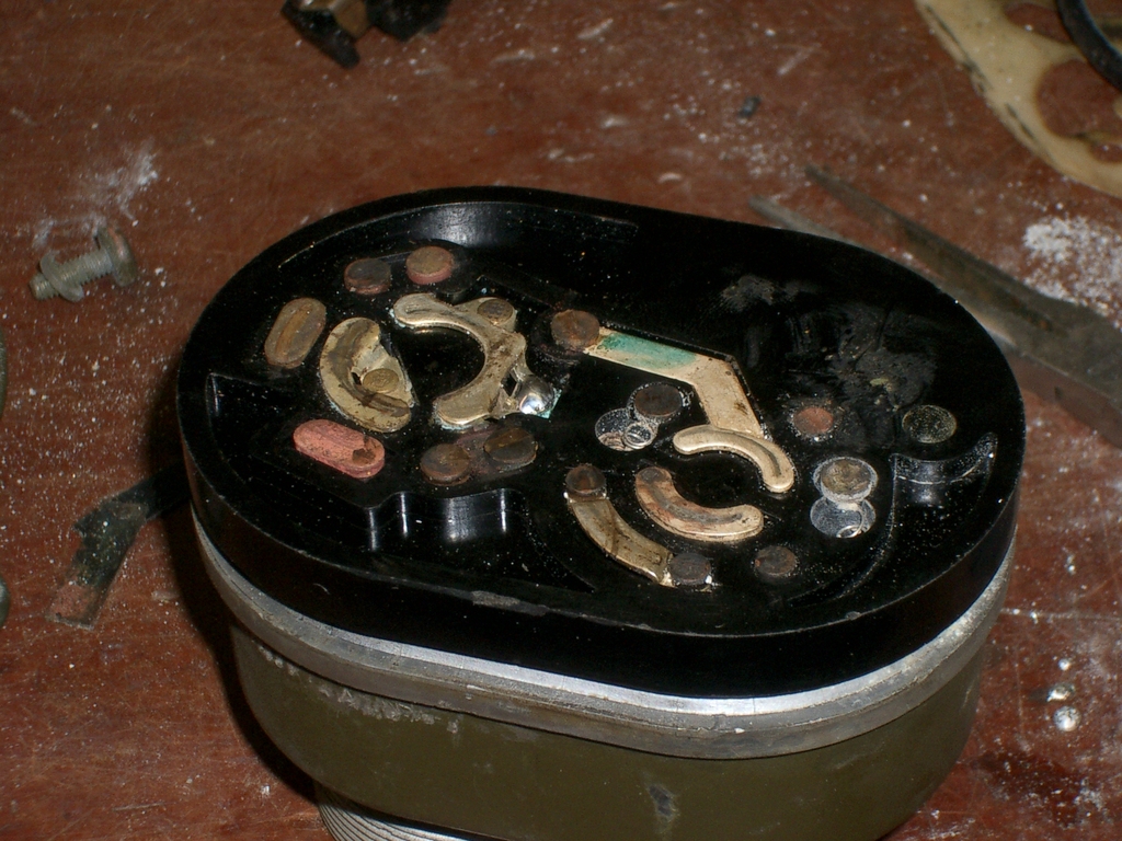
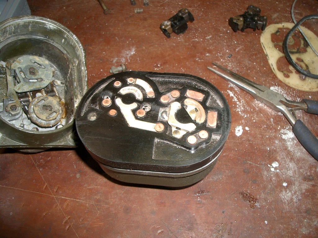
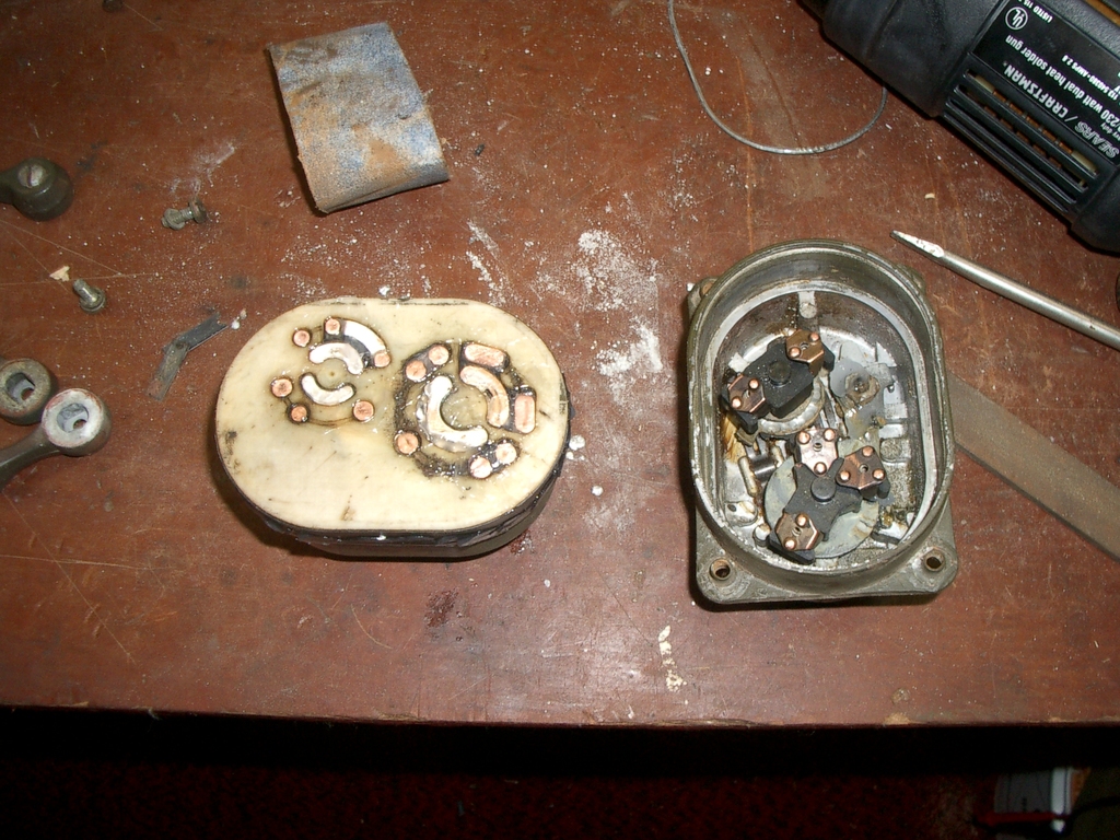
Here's more views, showing how it's put together:
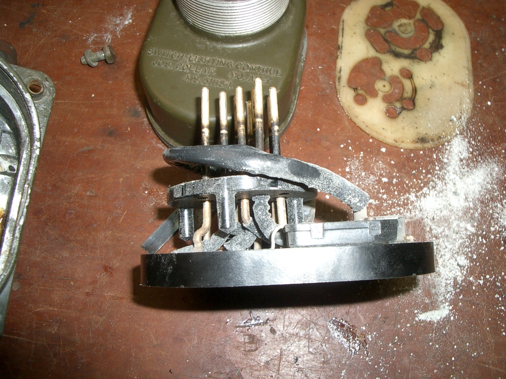
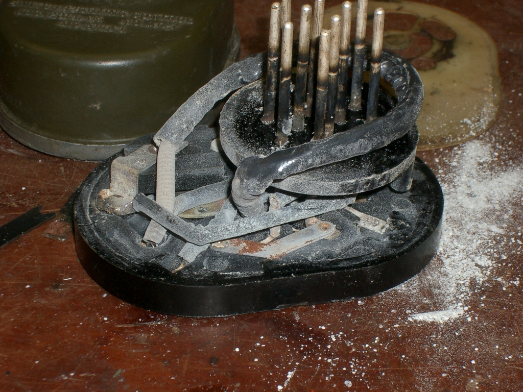
The long loop around everything is the resistor for the panel dim setting - be careful with it, as it's hair thin wire. The black block on the lower right is the circuit breaker, with the contacts
underneeth it.
Repairing broken pins
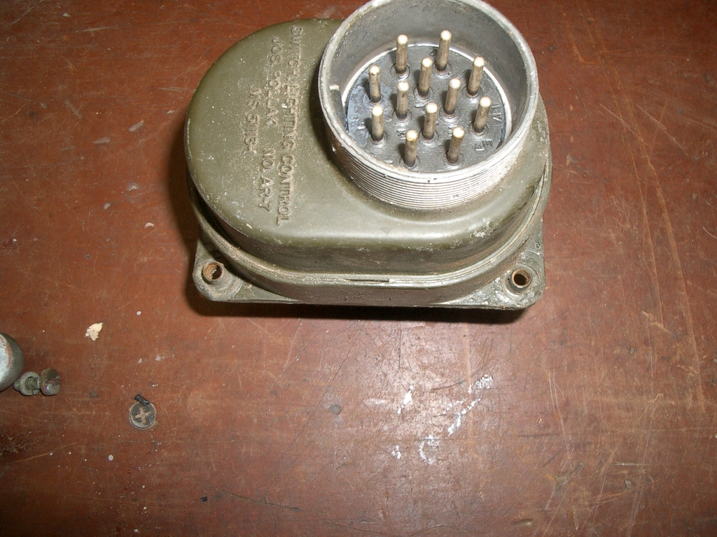
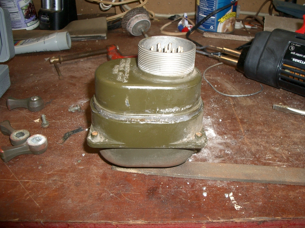
Hopefully you can skip this step - and if you do find a switch like mine, go buy a new one! However, I wanted to get this one working, so I went ahead and fixed the broken pins. When I pulled the inside
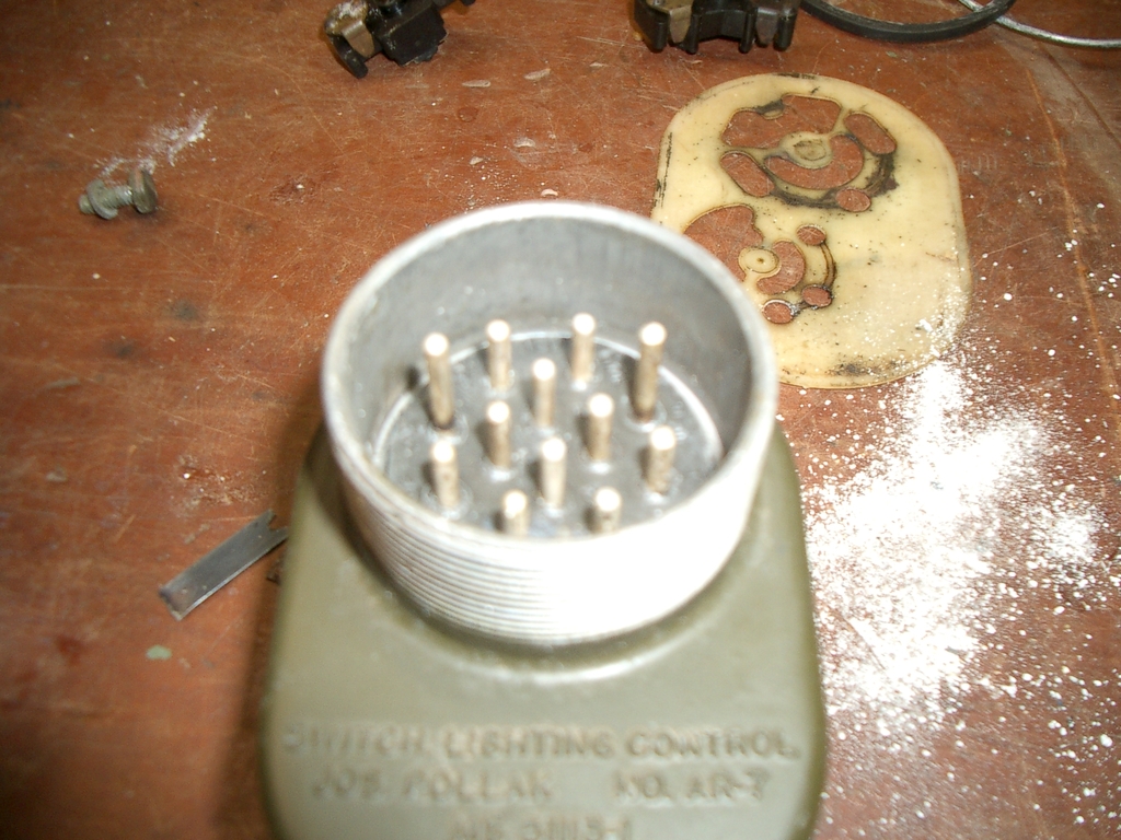
out, the plug looked like...
And the inside...
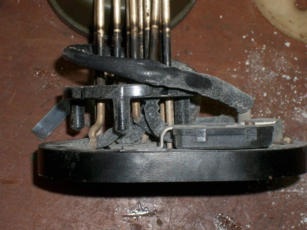
D'oh! Well, at least that explains why going over bumps and wiggling things always made all the lights flicker! The ends of the pins are both corroded from years of being broken, and burnt from frequent
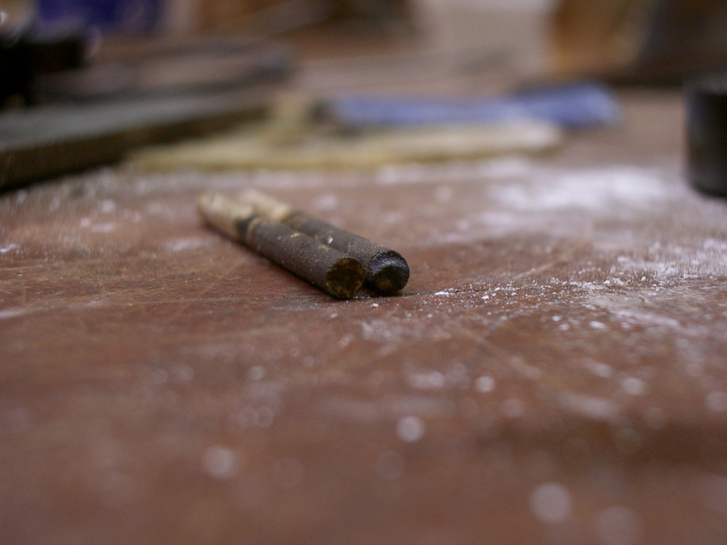
arcing. I had two contacts completely broken off, and one almost broken all the way through - you can see it crooked in a lot of the images. Here's the main power feed:
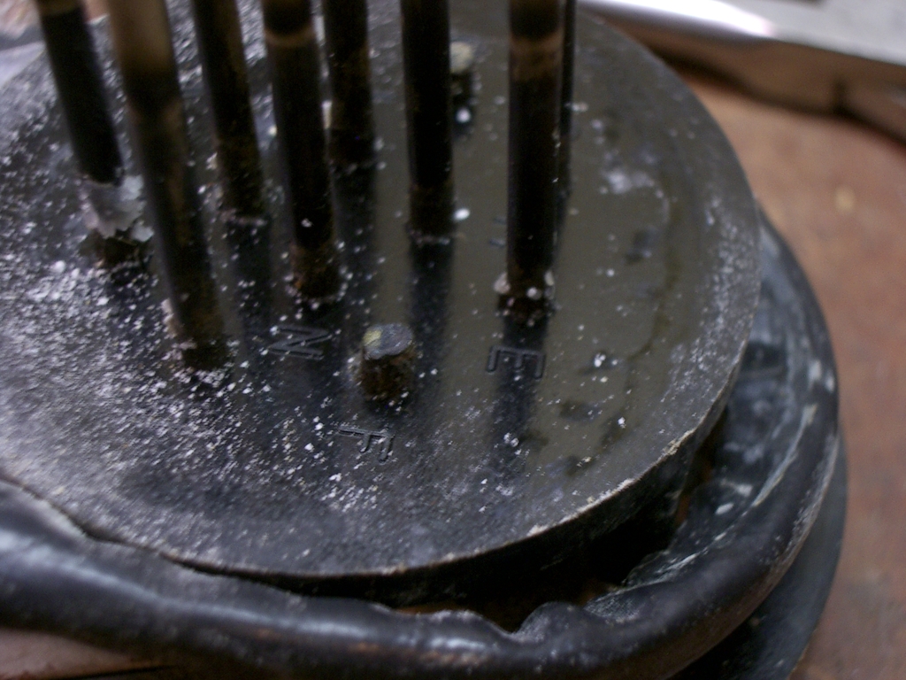
"Well there's yer problem!" And here's the mostly broken one:
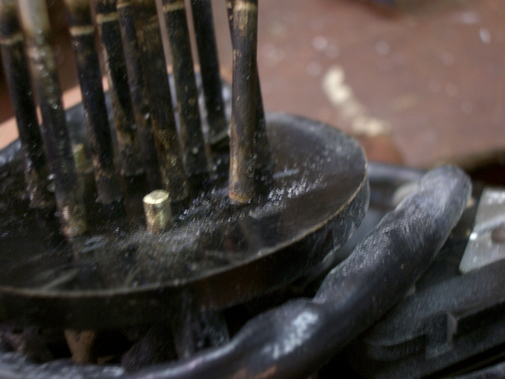
And the two pins.. note the pitting from arcing every time my lights blinked:
First step, clean them up nice and shiny:
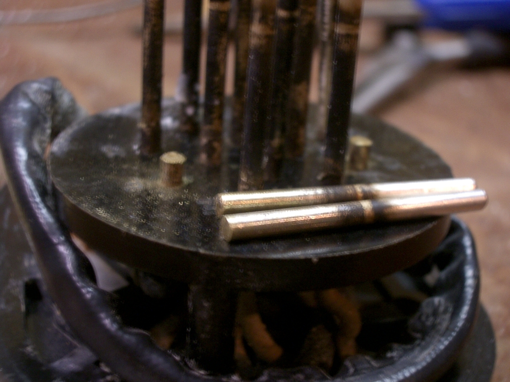
And then solder them back onto the stubs:

Again, if your switch also has broken pins, getting a new one is probably a better bet - getting solder to wet these was a pain, and the life expectancy of the fix is unknown.
Cleaning the circuit breaker
Many people have problems with the circuit breaker - the contacts get dirty or worn, causing the bimetal strip to heat up quicker, and trips at incresingly lower currents every time. Easy enough to fix -
use a small screwdriver, and stick some sandpaper in:
Slide it back and forth, wiggle it around, etc. Then flip the sandpaper over and repeat to get the other contact. When that's done, use a piece of cardboard to do the same:
This will get out any little particles that could keep the contacts from closing properly.
If you're running a 12V system, you could either drill out the rivets and use a larger circuit breaker in its place (miniature ones, smaller than the one used in the switch stock, are available in 20A
and 30A at most auto part stores, which should be plenty for most 12V conversions), wire up a second circuit breaker in parallel (they'll share the load, or at least mostly share it), or jumper the
circuit breaker with a piece of wire and use an inline fuse or circuit breaker in the wiring harness before it feeds the switch.
Re-assemble the inner half
Once you've cleaned or replaced the circuit breaker, it's time to put the inside back together. Start by healthly greasing the rubber plug with any dielectric grease:

The grease will both aid insertion and make sure it's waterproof. Carefully insert the inside, making sure to line the pins up with the holes, and gently press it through.
Clean the contacts
Your contacts are probably dirty, burnt, or otherwise a problem. Take the inside...
And flip it upside down and run it on a piece of sandpaper:

Then get any places that didn't get by hand, and you'll have shiny contacts: (I also soldered a rivet with a corroded-away head to the contact it feeds)
The wiper contacts look like:

Each one has a small spring to press it against the contacts. Remove them, replace any broken springs, and rub the sandpaper on them by hand. Don't use a flat surface like for the other contacts - you
want these to be rounded, not flat - just use your finger to press the sandpaper into them. Put the contacts back on the plastic arms with a spring under each one, and make sure they move freely. If
they bind, try rotating it 180 degrees, or swapping them around with others of the same type,
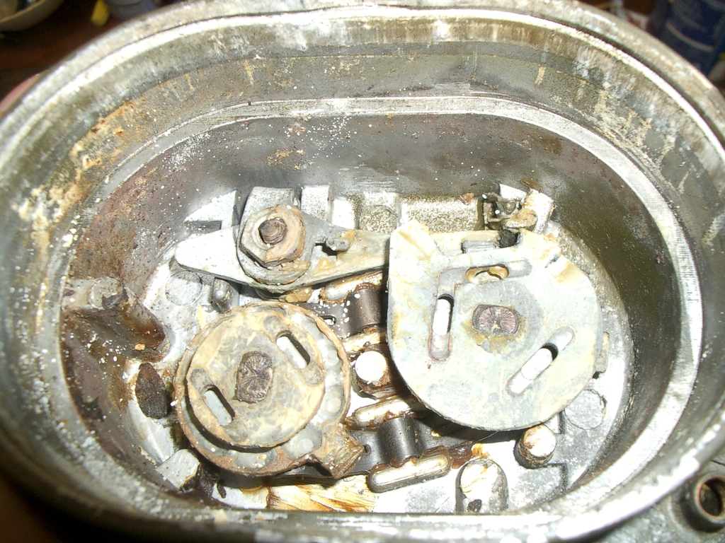
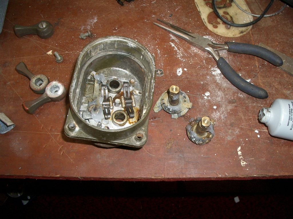
Grease the internals
Go back to the other half of the switch, and clean out as much crud as you can, being sure to get the mating surface of the two halves clean:
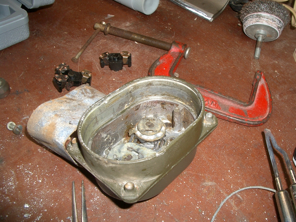
Remove the two switch shafts, and clean them too. Then, using any good grease, get all the moving parts:
Put some dielectric grease around the contact pads on the back half, then put the white plastic sheet on top, then liberally grease the paths the wipers rotate in. The grease on the back will hold the
plastic in place during re-assembley, and make life a lot easier!

Putting it back together
First, put your wiper arms back on the lever shafts:
Pop the big O-ring back in its groove, and apply more grease:

You should now have two halves - do a check of the workbench for any parts that escaped....
Flip the back over, and start inserting it into the top. Be sure not to bump the bottom half or turn it sideways or upside down, or all the little contacts will fall off, and you'll have to take it back
apart to put them back in place.
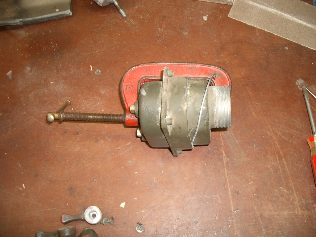
Start pushing the halves together. The O-ring will probably catch, so you'll need to go around the edge and pop it down into the housing. Since you're fighting a lot of spring pressure, it's time for
the C-clamp again. I got out a nice big one, and used a small screwdriver's handle as a spacer so I didn't press against the lever shafts:

Gently tighten the clamp, being sure the O-ring doesn't get pinched, until the two halves are back together. At this point it can be turned sideways again or moved around, as the contacts are now firmly
in place. Start the snap ring on one side:

And work around pushing it in. If it pops up like this when you remove the clamp....
You probably didn't have the clamp tight enough, or you deformed the snap ring prying it out, in which case you need to carefully bend it back into shape. It took me a lot of wrangling to get it back
together, so take your time, and be prepared to pop the snap ring in and out a bunch of times...
Yay! If all went well, you have one of these again:
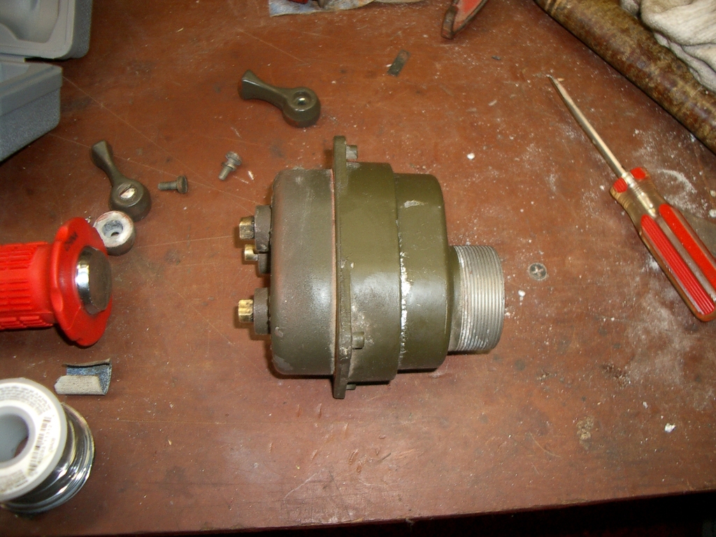
Re-install and test
Take it back out to the jeep, push it through the hole in the dash, re-install the four screws, re-install the levers, screw the plug back on, and it's time to test it out!
Flip it through all the settings, making sure every light works, and go for a drive to make sure your switch is nice and reliable - after all, not buying a new switch gets you almost a tank of gas! (If
you have a jeep, not anything larger, obviously...)
Final thoughts
I hope this writeup helps someone - enjoy!
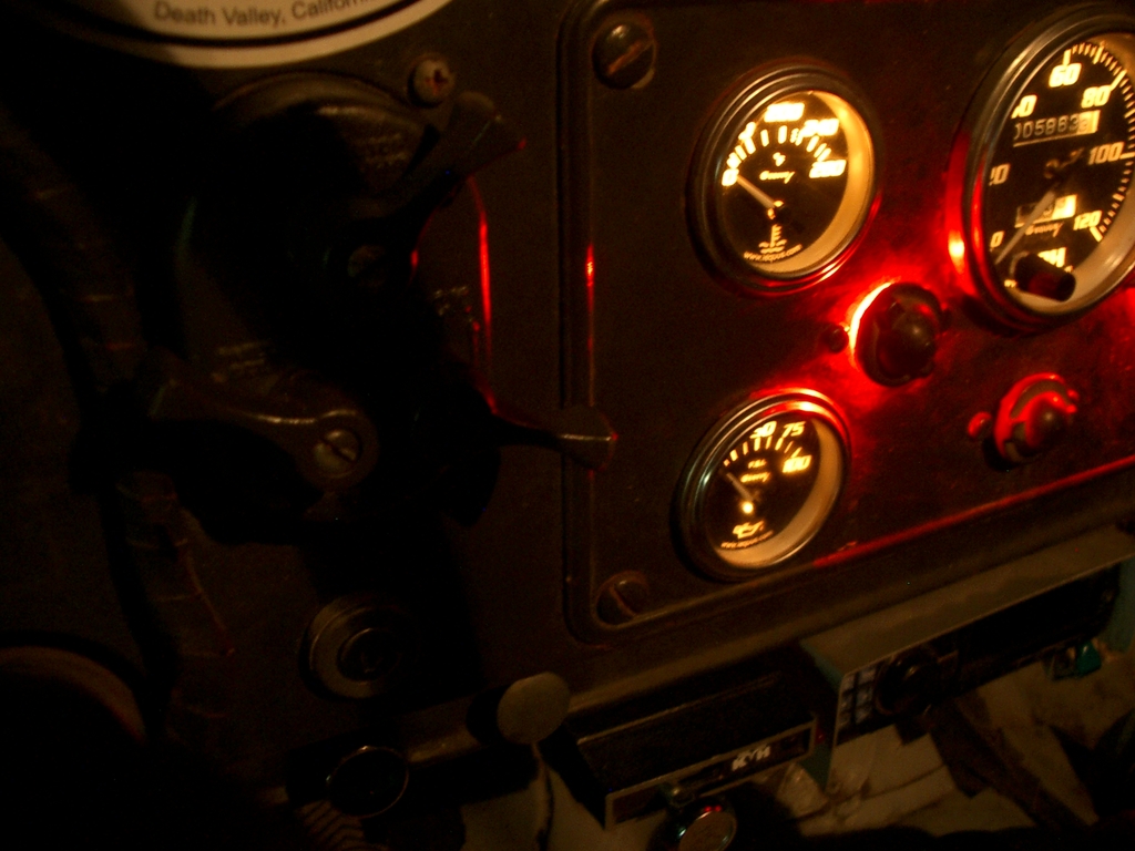
And yay! I have lights again!